The Block Driver
Theory : Virtio Protocol
references :
VirtIO protocol is a communication protocol. It defines how a virtual machine communicates with a hypervisor.
Okay... now you are asking "what do virtual machines and hypervisors have to do with us? we were just here chilling and talking about bare-metal operating systems!"
The thing is that Virtio protocol uses VirtIO devices. Virtio devices are virtual devices that have a simple standard interface. For example, it defines network cards and hard disks. Qemu uses the VirtIO protocol to define some of its this devices.
VirtIO is more than a commuication protocol, it also defines the API of a virtual device. So you can be assured that devices that use the VirtIO standar will have a similar API. From this perspective, virtio is a protocol for abstracting devices.
In our case, we will act as the VM that is in need of virtual devices.... and Qemu will act as the Hypervisor that exposes the underlying hardware using the VirtIO specifications.
We will deal with virtio block devices. We will write a driver for a Virtio Block device.
How Qemu exposes VirtIO devices
As earlier said, there are many kinds of virtIO devices; network cards, hard-disks, GPUs.... any device that can be eventually abstracted.
Qemu exposes the virtIO devices below :
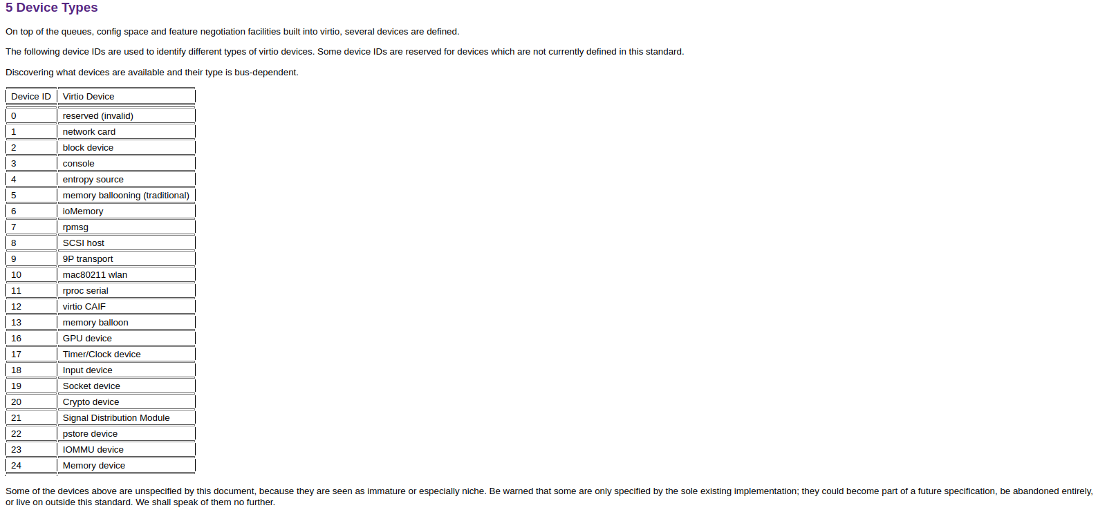
Qemu exposes these devices in the MMIO dedicated memory section. It puts the above virtio devices (backwards) from 0x1000_1000 to 0x1000_8000. For example if we decide to attach only one virtio device, we will attach it at 0x1000_8000 instead of 0x1000_1000.
Qemu supports 8 Virtio buses. Each having 4096 byte register space.
We use MMIO programming to communicate with the underlying Virtio devices
MMIO registers for Virtio in Riscv are 32 bits each.
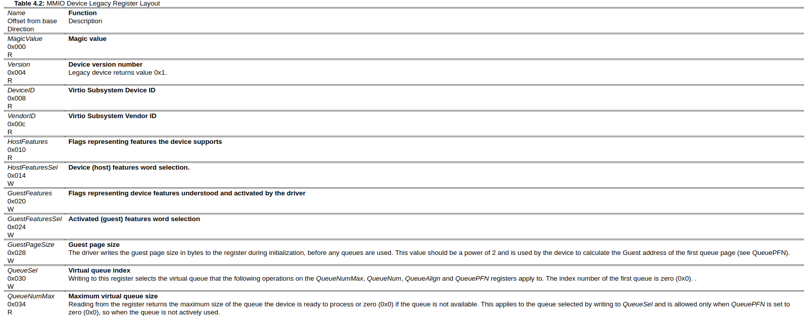
Qemu uses the legacy version of VirtIO protocol. Meaning that the offsets of the registers differ from the modern version.
The Communication Protocol
THe Queues of message passing
In the context of a VirtIO device, a queue refers to a data structure used to facilitate communication and data transfer between the guest operating system (running in a virtual machine) and the host system (the hypervisor or virtualization layer). These queues are particularly important for devices that involve asynchronous communication, like network adapters and storage devices.
The queue consists of two main components:
Descriptor Table: This table contains a set of descriptors that describe the buffers where data will be read from or written to. Each descriptor points to a memory buffer in the guest's address space. These descriptors include information such as the physical address of the buffer, the length of the buffer, and flags indicating the purpose of the buffer (e.g., input or output).

Available and Used Rings: The available ring is used by the guest to communicate to the host which descriptors are ready to be processed. The used ring is used by the host to indicate which descriptors it has processed. Both the available and used rings are essentially arrays of indexes into the descriptor table. These rings allow for efficient asynchronous communication, as the guest can put descriptors into the available ring for the host to process, and the host can place used descriptors into the used ring for the guest to acknowledge.
Here's how the queue works in a nutshell:
1. Guest Prepares Descriptors: The guest prepares one or more descriptors that point to memory buffers containing data it wants to send to the device (for output) or to receive data from the device (for input).

2. Guest Updates Available Ring: The guest places the indexes of the prepared descriptors into the available ring. This informs the host that there are descriptors available for processing.

3. Host Processes Descriptors: The host periodically checks the available ring to see if there are any new descriptors. If there are, the host processes the data according to the descriptor's instructions.

4. Host Updates Used Ring: After processing the descriptors, the host updates the used ring with the indexes of the processed descriptors. This signals to the guest that the data has been processed.

5. Guest Acknowledges: The guest periodically checks the used ring to see which descriptors have been processed by the host. Once the guest acknowledges the processing of descriptors in the used ring, the host can reuse those descriptors for future communication.
This queue-based approach allows for efficient and asynchronous communication between the guest and the host, reducing the need for constant synchronization between the two. It's a key mechanism in VirtIO devices and is designed to optimize data transfer between the virtual machine and the host system.
Interrupt Handling
Here is the step by step flow of events hen an interrupt happens :
1. Interrupt Generation: The VirtIO device generates interrupts to signal the guest about specific events or conditions that require the guest's attention. These events could include data arrival, data processing completion, or other situations where the device needs to notify the guest.
2. Setting InterruptStatus: When an event occurs that warrants an interrupt, the VirtIO device sets specific bits within the InterruptStatus register (at offset 0x060). Each bit corresponds to a particular event.

3. Guest Checks InterruptStatus: The guest periodically checks the InterruptStatus register to determine which interrupt events have occurred. If the guest detects that certain bits are set, it means that there are pending events that need to be handled.

4. Event Handling: In response to detecting set bits in the InterruptStatus register, the guest performs the necessary actions to handle the corresponding events. For instance, if a bit indicates new data arrival, the guest might initiate data processing routines.

5. Using InterruptAck: After the guest has successfully processed the events and taken the appropriate actions, it writes to the InterruptAck register (at offset 0x064). The value written to this register is typically a bitmask that corresponds to the events that have been acknowledged and handled.

6. Clearing Interrupts: Writing to the InterruptAck register clears the corresponding bits in the InterruptStatus register. This clearing of bits indicates to the VirtIO device that the guest has acknowledged and dealt with the events associated with those bits.

Acknowledgement Protocol: The act of writing to the InterruptAck register is the guest's way of formally acknowledging that it has received and processed the interrupts. This protocol ensures that the guest and the VirtIO device are in sync regarding the status of the interrupts.
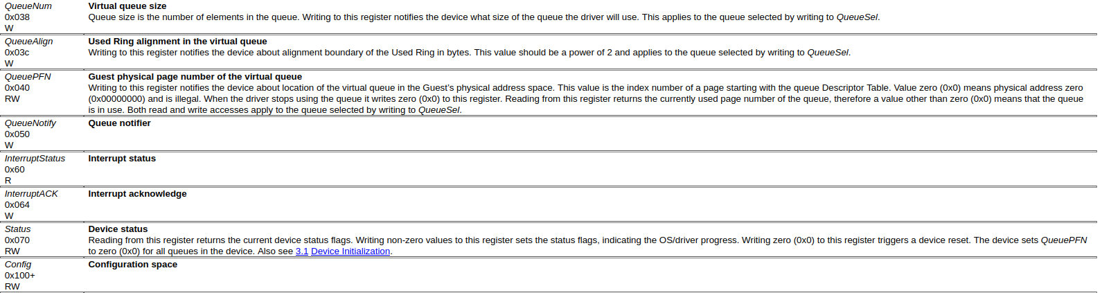
How the Layout of a VirtIO MMIO looks
Abstracting the MMIO Bus address full of registers in Rust
#![allow(unused)]
fn main() {
// Below are offsets
#[repr(usize)]
pub enum MmioOffsets {
  MagicValue = 0x000, // identifies the protocol used to abstract and communicate with the device. The value "triv" symbolises that the device uses VirtIO protocol. "triv" is the little endian version of thr word : "virt"
  Version = 0x004,  // Stores the version of the VirtIO specification that the device adheres to. We use version 1 : 0x001
  DeviceId = 0x008,   //  holds a value that uniquely identifies the specific VirtIO device.
  VendorId = 0x00c, // Similar to the device ID, this register holds a value that identifies the vendor or manufacturer of the VirtIO device
  HostFeatures = 0x010, //  represents a set of feature flags that the host supports.
  HostFeaturesSel = 0x014, // A selection register that indicates which set of feature flags (lower or higher) the guest should use to negotiate features with the host.
  GuestFeatures = 0x020, // The guest uses this register to indicate which features it supports to the host
  GuestFeaturesSel = 0x024, // Similar to HostFeaturesSel, this register selects which set of guest feature flags (lower or higher) to use for feature negotiation.
  GuestPageSize = 0x028, // specifies the page size that the guest expects for its memory buffers
  QueueSel = 0x030, // A selection register for specifying which virtual queue (used for communication between host and guest) is currently being operated on.
  QueueNumMax = 0x034,  // Indicates the maximum number of queues supported by the device.
  QueueNum = 0x038,  // This register holds the actual number of queues that are being used by the guest. It might be less or equal to QueueNumMax
  QueueAlign = 0x03c, // Specifies the alignment requirements for queue descriptors and available/used ring entries.
  QueuePfn = 0x040, // Page Frame Number (PFN) for the physical address of the queue.
  QueueNotify = 0x050, // This register is used to notify the host about new available descriptors in the queue. The Host periodically checks the QueueNotify Register
  InterruptStatus = 0x060, // : Indicates the status of interrupts from the device to the guest. Host modifies the value, guest reads ONLY
  InterruptAck = 0x064, // The Guest acknowledges that it has handled an interrupt by writing the Interrupt ID to this register. The Host then modifies the InterruptStatus register
  Status = 0x070, // The Status register (at offset 0x070) in the context of a VirtIO device represents the current operational status or state of the device from the perspective of the guest operating system (running in a virtual machine). This register allows the guest to query and manipulate the state of the VirtIO device as it relates to its own operations and interaction with the device.
  Config = 0x100, //This register points to the configuration space of the VirtIO device, allowing the guest to access and modify configuration settings.
}


}
Implementation
1. Probing for a block device
As a good OS practice, we probe the MMIO space and determine which virtIO devices have been attached.
We then further check if there is a block device. A block device is a storage medium that allows access and fetching of its data in chunks. It also allows random access of those blocks. An example of a block device is an SSD storage or a HDD Hard-disk.
The Probe Function - We first need to scan the buses dedicated to connecting the virtio devices (from 0x1000_1000 to 0x1000_8000) and check which devices is attached to each bus
- loop through the buses in a bus-wise fashion
- confirm that indeed each bus is a virtio bus address by reading the magic value. Magic Value should be "triv"
- check if a device is connected to the bus. (if device_id > 0)
- Check the type of device attached to the bus (device ID 2 == block device)
- If we find that the bus is a virtio bus and device id 2, we can configure this device as a block device.
2. Configuring the Block device (Negotiation)
configuring the device (initializing_the_device)
Before we use the device(any device in the world), we must set the right configurations by adjusting the values in the MMIO registers.
These steps are commonly referred to as the "initialization handshake". They are used to establish communication between the driver and the device.
Both Guest and Host need to negotiate.
The steps for configurating a device are laid out in the virtio specification as (source):
pre-requisites :
- Reset the device by writing 0 to the Device status register. Resetting means setting values to known default values. This removes any uncertainities or unpredictable behaviour, we begin our communication on a clean slate. No surprises.
- Reading from the Device status register returns the current device status flags.
- Writing non-zero values to this register sets the status flags, indicating the OS/driver progress.
- Writing zero (0x0) to this register triggers a device reset. The device sets QueuePFN to zero (0x0) for all queues in the device.
- Set the ACKNOWLEDGE status bit to the status register.
- within the device status register, there is a single bit called the Acknowledge status bit.
- The Acknowledge status bit value is 1 when both the driver and device agree that they are connected to each other and can continue with initialization. This bit answers the question "Are we connected to each other? And are all of us okay with this connection?"
- The driver sets the Bit to 1 to acknowledge that it has access to the device registers and has found it to be a valid virtio device(connected).
- The device reads, the bit and also redrive first and then attach it to a specific interface later using a separate -device option.sets it to 1 to confirm that it is okay with the connection.
- The device cannot reset the bit to 0. If an error occurs within the device and the device is not okay with the connection, it sends a message through other status bits such as DEVICE_NEEDS_RESET or DEVICE_FAILED bits, to indicate that the initialization process has failed and needs to be restarted in order to create a proper connection.
- Set the DRIVER status bit to the status register
- The driver status bit indicates that the Guest has a driver that can drive the device.
- After the driver sets the Acknowledge bit to 1, it sets the DRIVER status bit to 1 to indicate that it is in control of the device and is ready to negotiate the features that the device supports. The device then acknowledges this by setting the ACKNOWLEDGE status bit to 1 and waits for the driver to read the device features from the host_features register.
- Read device features from host_features register.
- Here are the Features of the virtio block device
- Each virtio device offers all the features it understands. During device initialization, the driver reads this and tells the device the subset that it accepts. The only way to renegotiate is to reset the device.
- This allows for forwards and backwards compatibility: if the device is enhanced with a new feature bit, older drivers will not write that feature bit back to the device. Similarly, if a driver is enhanced with a feature that the device doesn’t support, it see the new feature is not offered.
- Feature bits are allocated as follows: 0 to 23 Feature bits for the specific device type 24 to 37 Feature bits reserved for extensions to the queue and feature negotiation mechanisms 38 and above Feature bits reserved for future extensions. Note: For example, feature bit 0 for a network device (i.e. Device ID 1) indicates that the device supports checksumming of packets.
- Negotiate the set of features and write what you'll accept to guest_features register.
- The Guest_features register contains Write_only Flags representing device features understood and activated by the driver.
- Fill this out so as to establish compatibility between
-
Set the FEATURES_OK status bit to the status register '
- The FEATURES_OK status bit Indicates that the driver has acknowledged all the features it understands, and feature negotiation is complete.
- The driver sets the FEATURES_OK status bit to indicate to the Virtio device that it has negotiated a set of compatible features.
- During device configuration, after the driver negotiates the set of features and writes what it will accept to the guest_features register, the device checks if it can support the negotiated features. If the device does not support all the features negotiated by the driver, it may set the FEATURES_OK status bit to 0 to indicate that it cannot accept the negotiated features
-
Re-read the status register to confirm that the device accepted your features. The driver might have reset the Features_OK register to 0.
-
Perform device-specific setup - The driver performs any device-specific setup required to initialize the Virtio device, such as configuring queues and memory mappings.
- Set Queue Number register.
- The QueueNum is a register in the device's configuration space that specifies the maximum number of virtqueues supported by the device. By default, the Queue Number is set to 1...such that there is only one virtual queue occupying all of the buffer space.
- But you may need multiple queues to implement parallelism. So you will have multiple queues under the same buffer space.
- The Queue_Num_Max register is provided by the device (Read only), it specifies the total amount of parallel queues you can have
- VIRTIO_RING_SIZE is a constant defined in the VirtIO specification and represents the maximum number of elements (or "entries") in a VirtIO ring (default == 1024). A VirtIO ring is a data structure used by the VirtIO device and the driver to communicate with each other. It is a circular buffer of fixed size that is divided into two sections: the "available ring" and the "used ring".
- Set Queue Number register.
Actual : - step 7 : - read Queue_Num_Max register and see the max number of queues that is supported for parallelism - We randomly chose 1024 (VIRTIO_RING_SIZE) to be the number of parallel queues - We calculate the number of pages required to store the Queue structure for the block device. We add PAGE_SIZE - 1 to the size of the Queue structure (which is obtained using the size_of function), then divides the result by PAGE_SIZE to round up to the nearest page. The addition of PAGE_SIZE - 1 is to ensure that the calculation rounds up to the nearest page, so that there is no wasted memory. - We create space for the virtual queue in our driver. We do this by allocating pages that will be used by the queue - allocate memory for the queue and stores the physical address of the queue in the queue_pfn
- Set the DRIVER_OK status bit to the status register. The device is now LIVE.
- The DRIVER_OK status bit indicates that the driver is set up and ready to drive the device.
- The driver sets the DRIVER_OK status bit to 1 to indicate to the Virtio device that initialization is complete and it is ready to use the device.
Communicating
Now that the device is LIVE, we can start making requests by using the virtio rings.
The virtio descriptor/ring system is generic; however, we have a protocol when making block requests. We will make a block request using three descriptors:
(1) block request header
(2) block request buffer
(3) block request status.
The Block request header specifies the type of operation and the sector number
After the header, we store the data buffer. For reads, the device will write to this piece of memory, and for writes, the device will read from this piece of memory. It's important to note that these must be physical addresses, since the block device bypasses the MMU.
Finally, we have a status field. The device will write the result of the request to this 8-bit field. There are currently only three responses we can get: 0-success, 1-failure, 2-unsupported operation. That doesn't give us a lot of information, but if we get a 0, we can reasonably assume that our request was properly handled.
When making a request to the device, the memory we use to store the request must remain valid until the device has finished processing the request and has sent back a response. If we use memory that is allocated on the stack, it will be automatically deallocated when the function exits, which could lead to undefined behavior if the device tries to access that memory later.
To avoid this issue, we need to allocate heap memory to store the request. This memory will stay resident until we explicitly deallocate it, so we can be sure that it will remain valid until we have received a response from the device.
We will grab three open descriptors from the virtio queue, populate it with the header, buffer, and status, and then we write the virtqueue's number (0) into the queue_notify register to tell the device to start working on the request.
I will import the block driver... this block driver has too much detail[undone]n [ported]
Porting the Block Driver to our project
- The Block is attached as the first Virtio object. We know that Virtio objects are connected backwards (8, 7, ..., 1).
- So the block will be at block index 8
- We will assume that the Block Runs the MINIX file system. So by default, the first 1024 bytes will be dedicated to the SuperBlock. We will skip it. But we do not just skip only 1024 bytes, we skip 4096(a page that encompasses the superblock 1024 bytes)
How the Hard-Disk gets plugged
There was this Qemu configuration in our cargo.toml (cut-out) :
-drive if=none,format=raw,file=hdd.dsk,id=attic: This option configures a virtual hard drive for the virtual machine. It specifies that there's a drive with the ID "attic" and that the drive is not attached to any interface yet (if=none). The format of the drive is raw, and the drive data is stored in the hdd.dsk file.
drive <...options...> : This is used to define the characteristics of external storage devices and how they are connected to the motherboard. The options are listed below
if=none : The "if" stands for interface. It says that the storage device has not been connected to any interface of the motherboard.
if=nvme : Specifies that the storage device has been attached to the motherboard via the nvme interface (Non-Volatile Memory Express) interface, which is a protocol designed for high-speed SSDs.
if=scsi : Attaches the drive to a SCSI (Small Computer System Interface) interface, another type of disk controller used in various systems.
if=virtio : Attaches the drive to a VirtIO interface, which is a high-performance paravirtualized interface commonly used in virtual machines.
format=raw: This part of the option specifies the format of the virtual hard drive. In this case, raw indicates that the drive is in raw format, which means the data is stored directly on the disk without any additional formatting or container. Raw format is often used when working directly with disk images. Disk is abstracted as byte by byte. There are other formats that support more functionalities by default. For Example some formats support data comression, snapshots, encryption. Some of these formats include : vhdx and qcow2 (QEMU Copy-On-Write)
file=hdd.dsk: This part of the option specifies the path to the file that contains the virtual hard drive data. In this case, hdd.dsk is the file where the drive's data is stored.
id=attic: This part of the option specifies an identifier (ID) for the virtual drive. The ID is a user-defined label that can be used to reference this drive when attaching it to a virtual device interface later. In this case, the ID is set to "attic," which you can use to identify and attach this drive.
We also have the second part of the Configuration :
-device virtio-blk-device,scsi=off,drive=attic
-device:
virtio-blk-device: This part specifies the type of device you are adding. In this case, it's a VirtIO block device.
scsi=off: This part specifies the SCSI (Small Computer System Interface) emulation mode for the device. Setting it to off means that the VirtIO block device will not emulate a SCSI interface. Instead, it will use the VirtIO interface for communication, which is a more efficient and direct way of handling I/O.
drive=attic: This part specifies which drive (disk image) should be attached to the VirtIO block device. The attic value corresponds to the ID you assigned to the drive using the -drive option earlier in your configuration. This is how you connect a specific virtual drive to the VirtIO block device interface.